One Nucleo. Nine Instruments.
The essential measurement suite for every STM32 developer.
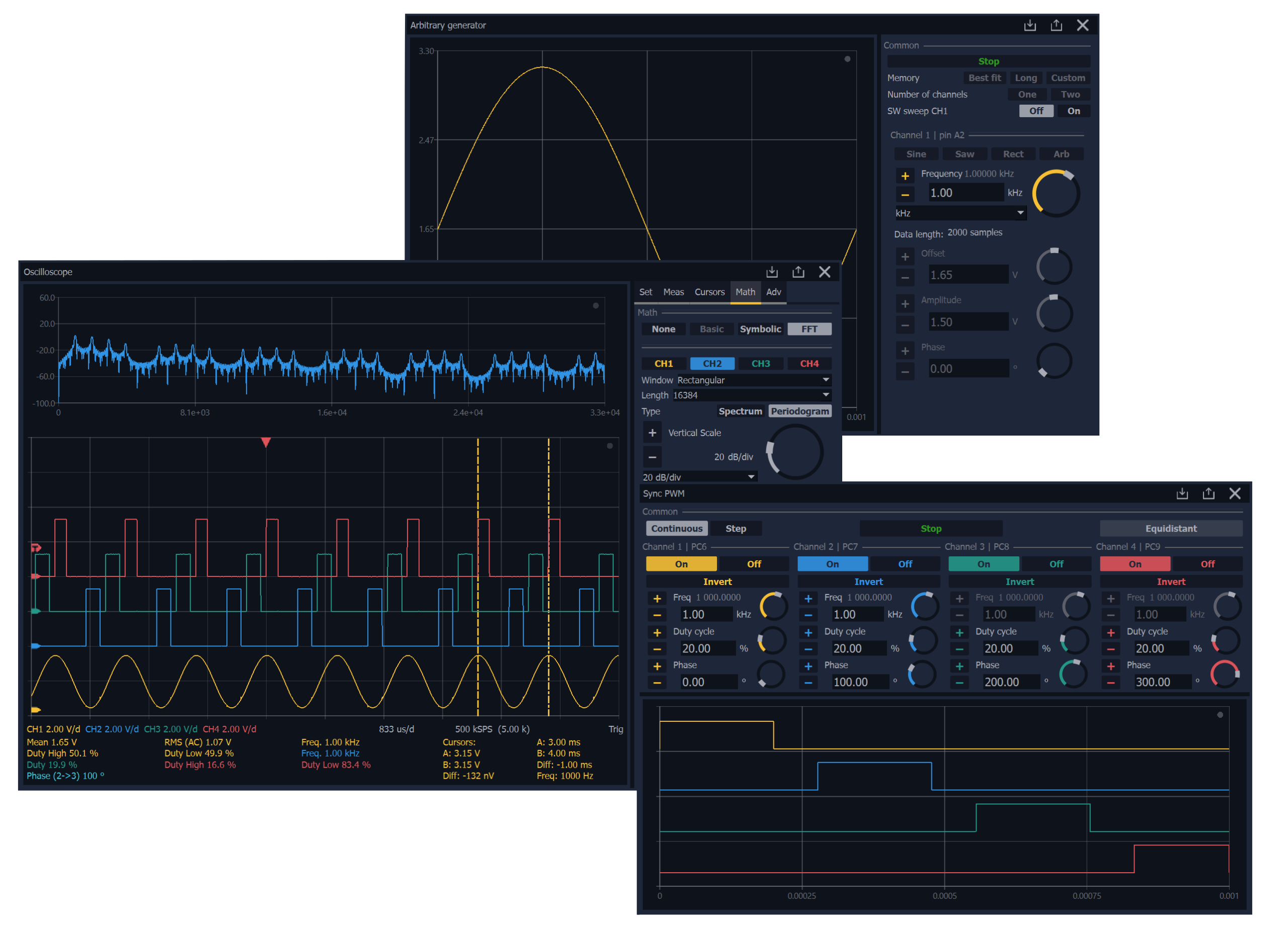
Everything on one screen
Sniffy is a modular software platform for signal measurement, analysis, and generation. It acts as a unified graphical interface for STM32 microcontrollers, combining the functionality of multiple laboratory instruments into one flexible control environment.
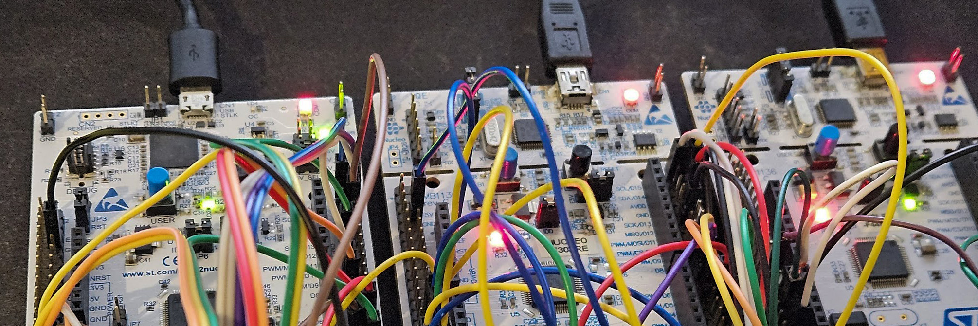
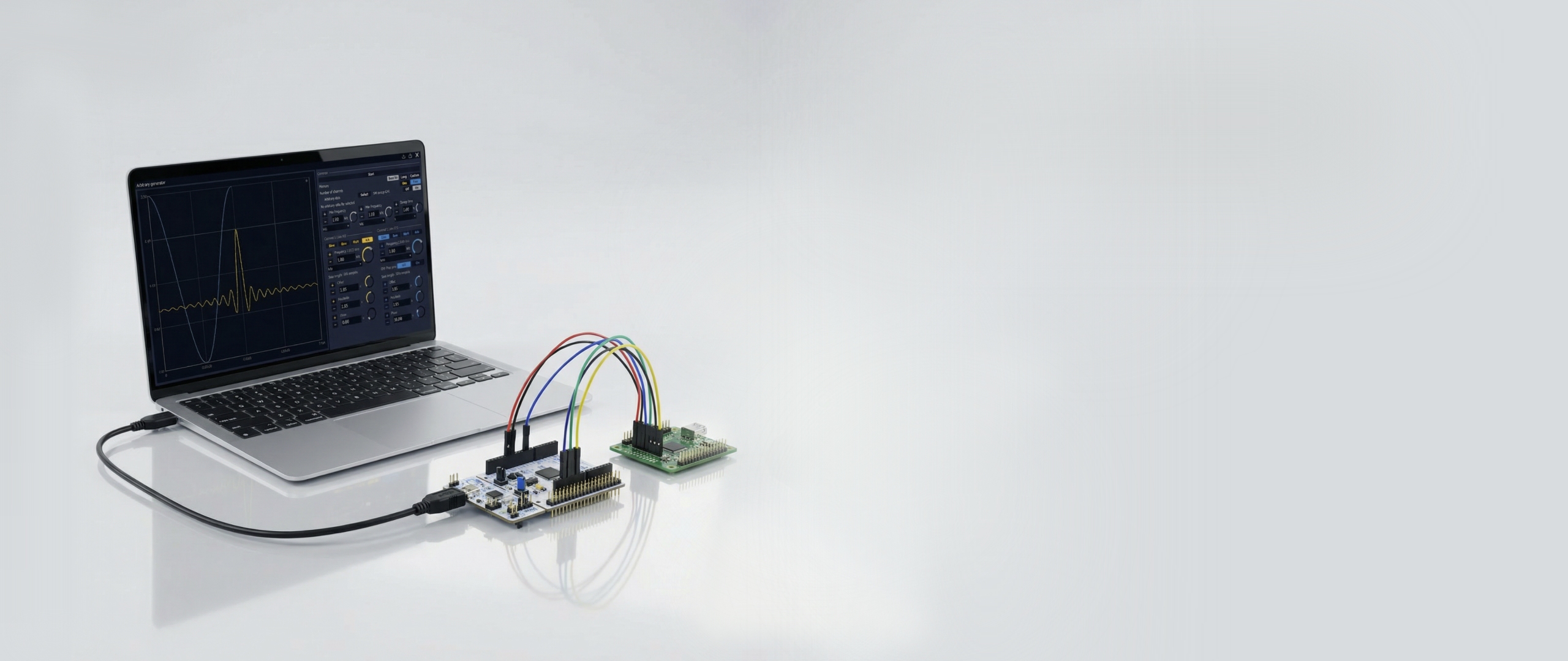
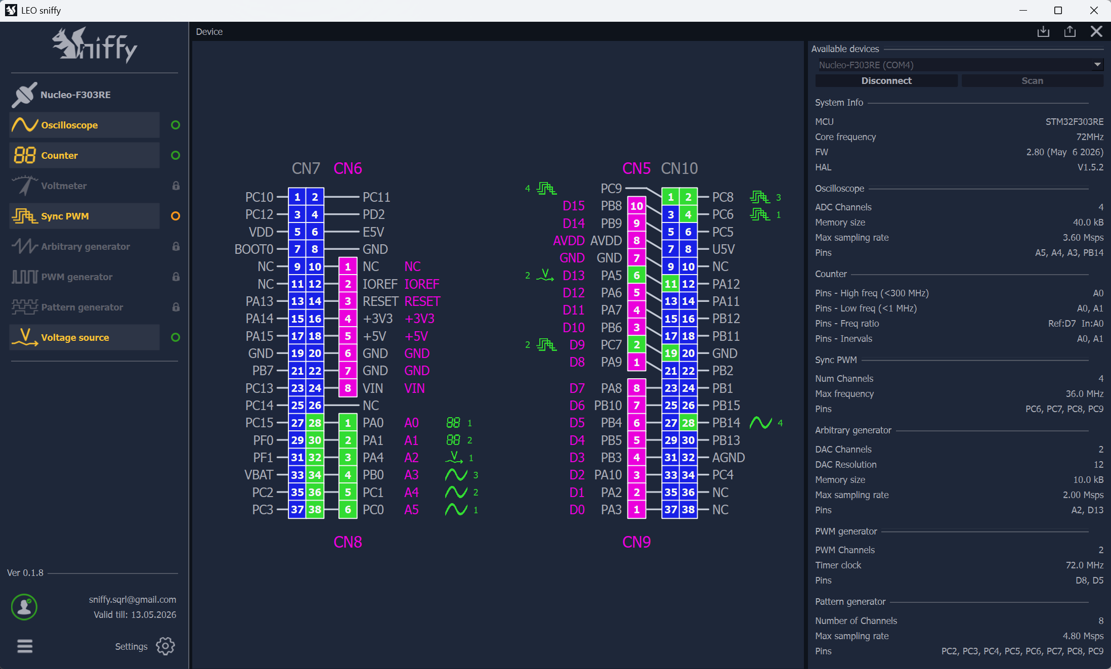
Wide hardware compatibility
Sniffy works on a wide range of NUCLEO development kits from STMicroelectronics with STM32 family chips. This eliminates the need to purchase expensive specialized hardware - often it is enough to take any available NUCLEO kit, upload the firmware and start measuring, testing and analyzing. Sniffy thus brings fast start, low cost and maximum flexibility in development and experimentation.
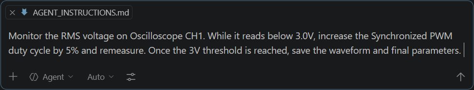
Tell it to your gadgets
Say goodbye to lengthy clicks through complicated menus. Thanks to our native integration Model Context Protocol (MCP) You can control an entire suite of measurement instruments using natural language. Watch as an AI agent autonomously evaluates live data and makes real-time decisions on the next course of action.
![]() Quick start
Quick start
![]() Low cost
Low cost
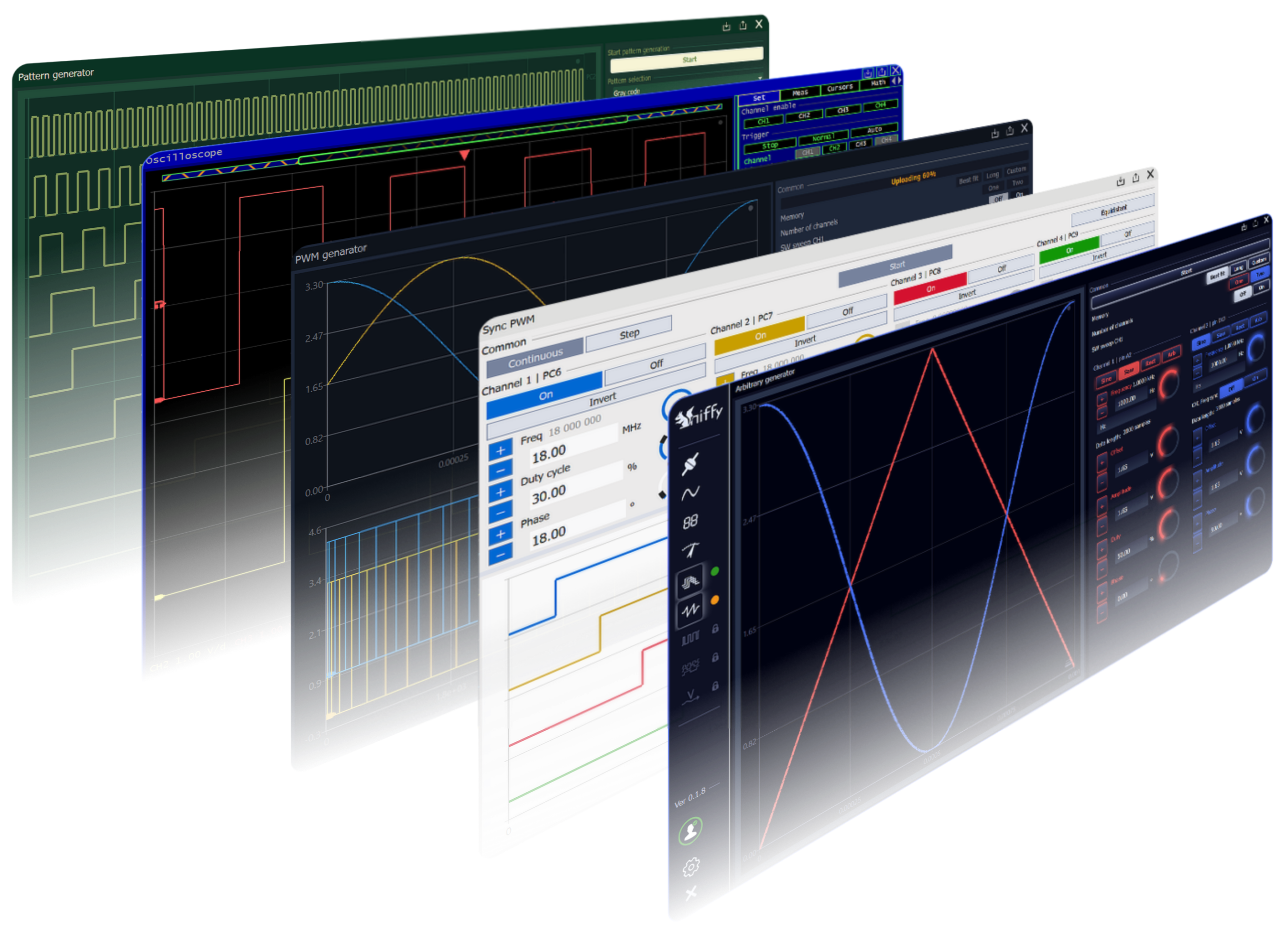
![]() All in one UI
All in one UI
![]() Wide compatibility
Wide compatibility
Overview
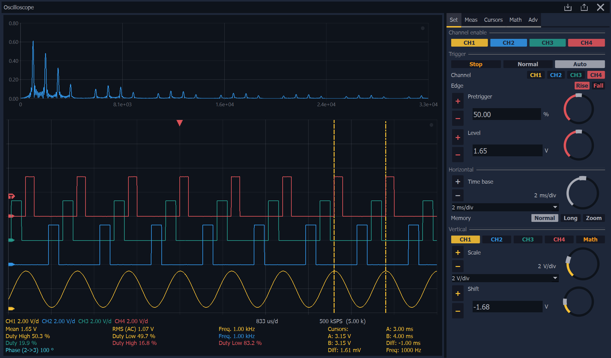
Oscilloscope
The oscilloscope is the main tool for real-time signal visualisation and analysis, with support for up to 4 channels. It offers comprehensive triggering options (Auto, Normal, Single) and adjustable timebase and vertical sensitivity. It includes automatic measurements (RMS, Peak-to-Peak, Frequency), cursor control, FFT spectral analysis, XY mode (Lissajous figures), and symbolic mathematical operations between channels.
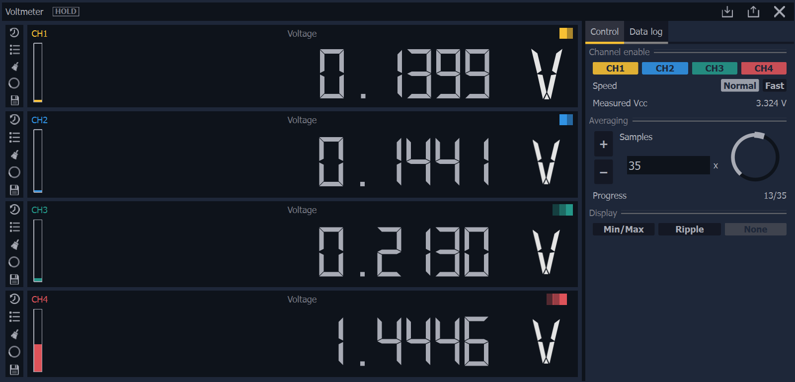
Voltmeter
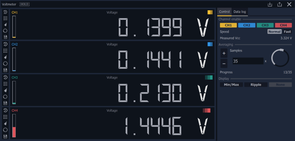
The voltmeter, designed for precise voltage measurement, offers a clear numerical display similar to benchtop instruments. It includes a history graph for tracking trends over time and a data logger for exporting long-term measurements to CSV files. It supports Min/Max value tracking, ripple measurement, and configurable averaging for smoothing noisy signals.
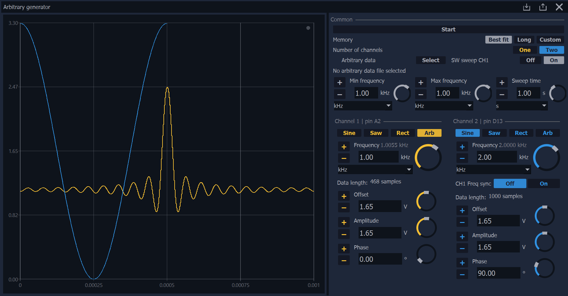
Signal Generator (ArbGen)
This module functions as a versatile function generator capable of producing both standard waveforms (Sine, Triangle, Square) and custom arbitrary signals. Users can fine-tune the frequency, amplitude, offset, and phase for each channel. It allows for the import of custom waveform data from CSV or TXT files. Furthermore, it provides a Sweep function, which enables the generation of a signal with a smoothly varying frequency, where the start and end frequencies (min/max) and the sweep time can be defined.
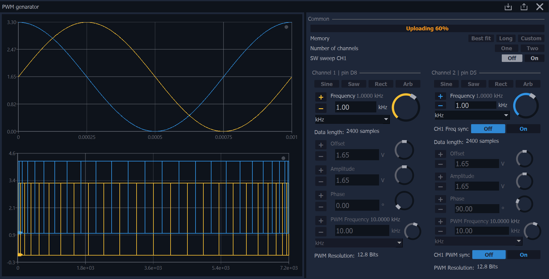
Modulated PWM generator (with variable duty cycle)

This module generates a PWM signal where the duty cycle dynamically changes over time according to a selected pattern. The duty cycle change can occur according to standard functions (Sine, Triangle, Square) or according to a user-defined custom arbitrary signal. It allows independent setting of the PWM carrier frequency and the modulation signal frequency.
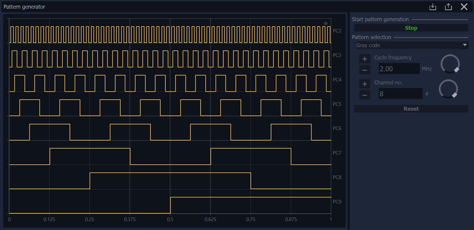
Generátor vzorů
The pattern generator serves as a source of digital logic, useful for testing digital circuits and communication buses. It can drive output pins with predefined sequences or algorithmic patterns. Modes include binary counter, Gray code generator, and user-defined sequences for custom logic states.
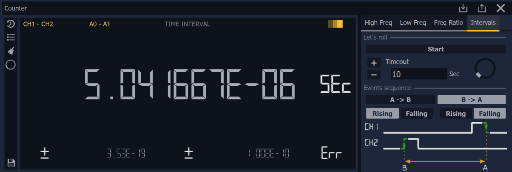
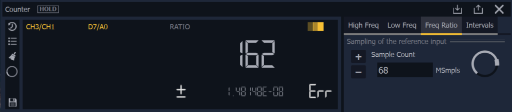
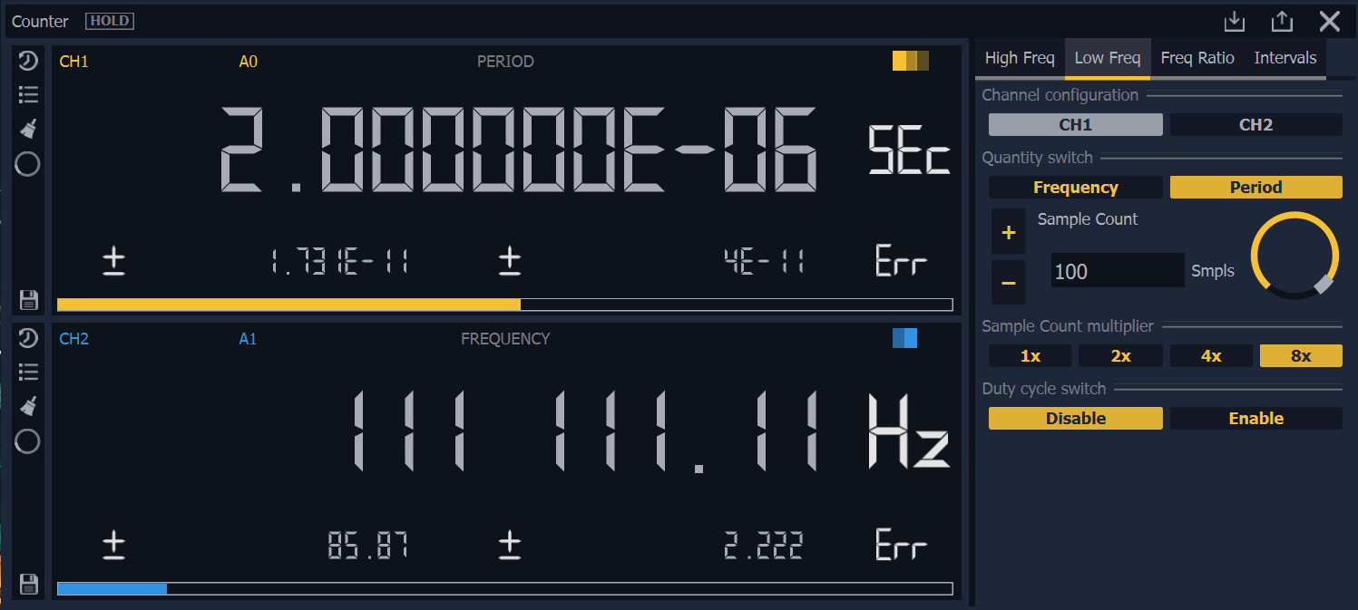
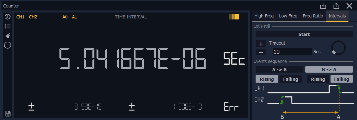
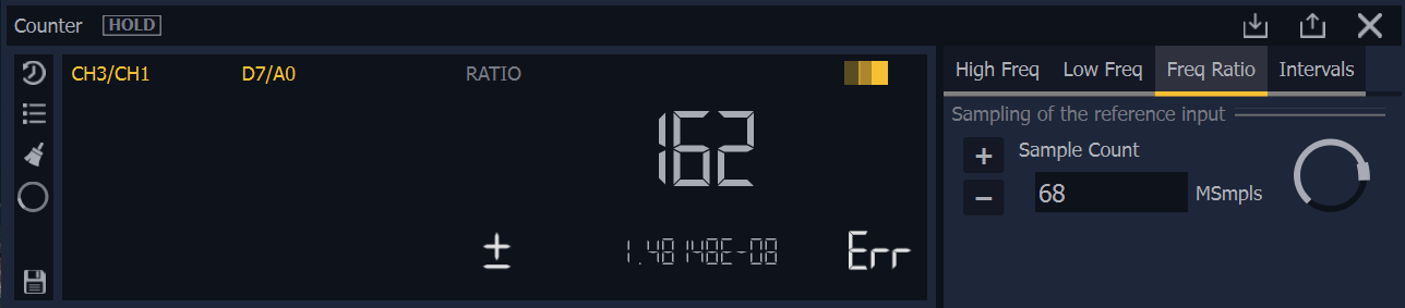
Counter
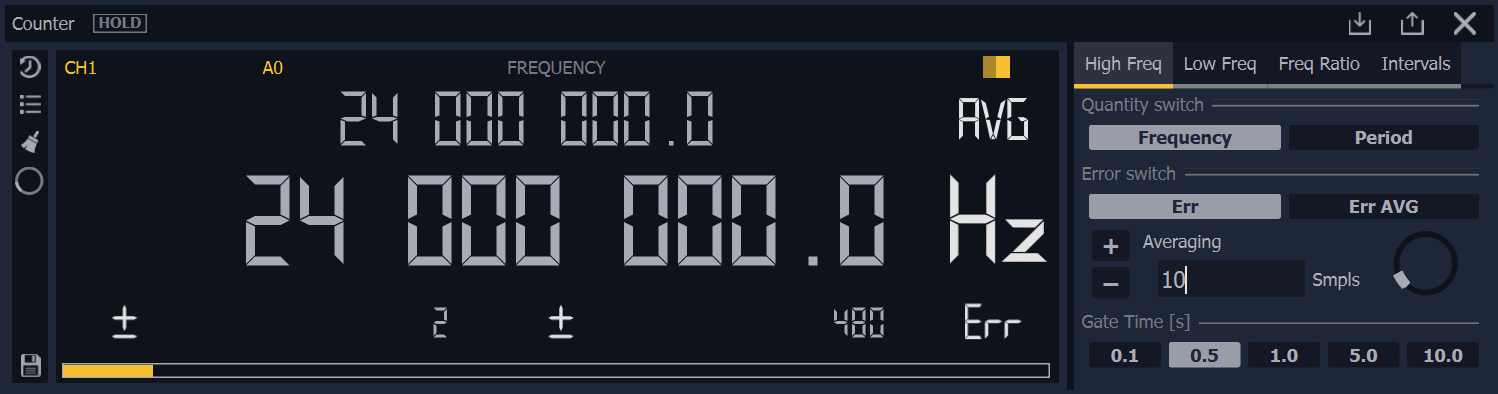
A specialised frequency and time interval counter for the analysis of external clock signals. It is optimised for various frequency ranges to ensure high accuracy. It offers HF mode (direct counting) for fast signals, LF mode (reciprocal counting) for precise frequency and period measurement, TI mode for time interval measurement, and Ratio mode for comparing frequencies between the internal and external channels.
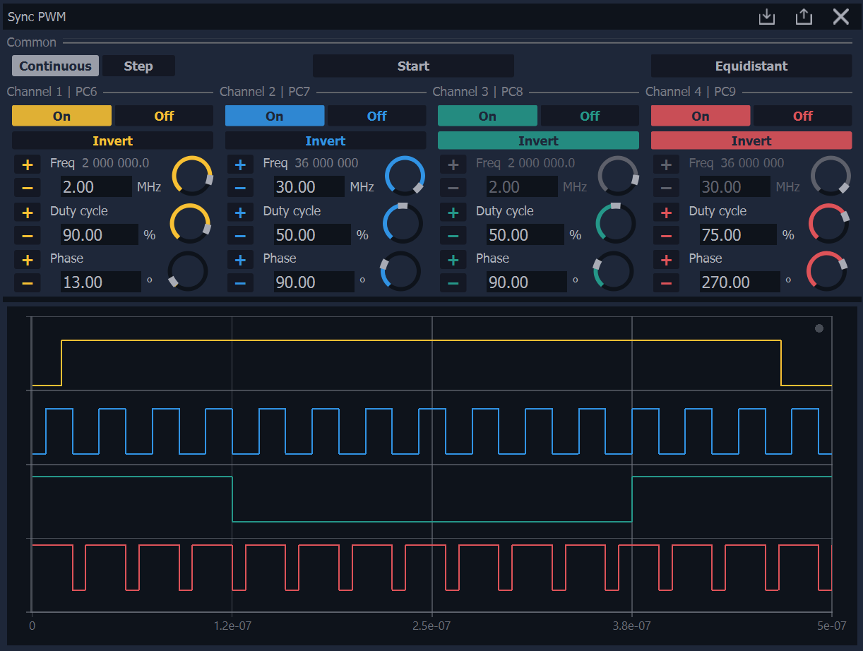
Synchronous PWM
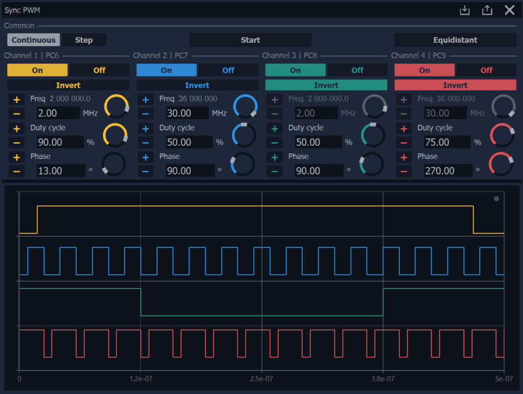
A specialised module that generates multiple pulse-width modulation (PWM) signals. It allows for precise control of the duty cycle and synchronisation between channels. It supports the configuration of dependent channels, phase shifting, and stepping modes for testing commutation sequences.
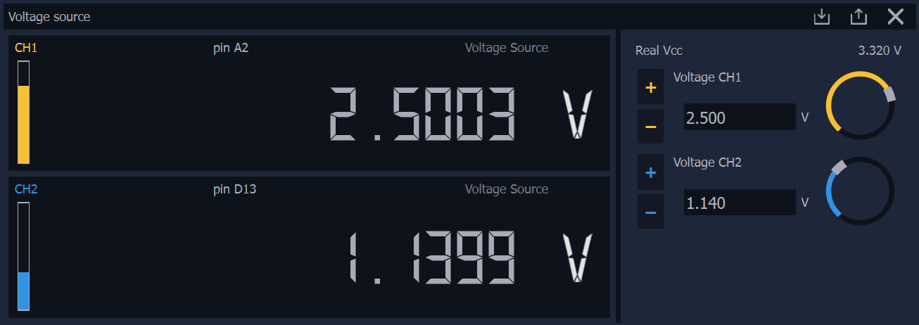
Voltage source
This module turns hardware into a programmable DC voltage source. It provides an interface for setting precise output voltages across multiple channels, which is useful for directly powering devices under test straight from the unit. It visualises real-time output monitoring (“Real Vcc”) with adjustable logic restrictions and safety limits.